
| China Electric Power Industry Standard―DL/T 1404-2 |
| 【author/from】webmanager 【time】2016/1/12 【count】2837 |
ICS 29.240.01
F21
Record Number: 50049-2015
DL
China Electric Power Industry Standard
DL/T 1404-2015
Technical Specification for Preventing Electric Mal-operation in Substation Monitoring and Control System
2015-04-02 Release 2015-09-01 Implement
National Energy Administration Release
Preface With the development of power industry, the function of preventing electric mal-operation in substation monitoring and control system is applied quickly in China. Up till now, there is no unified technical specification in the country. So it is necessary to make the power industry standards to achieve the design, construction and running of the system and make the research, production and running has unified standard. The standard is raised by China Electricity Council. The standard is explained by the National Power System Control and Communication Standardization Technical Committee. The advices in executing progress will be sent to Chinese Electricity Council Standard managing center. 1. Range This standard raises technical requirements of preventing electric mal-operation in substation monitoring and control system, the describing method of rules and relevant terms. This standard is used for the design and test of preventing electric mal-operation in substation (110kV or 66kV and above) monitoring and control system. The substation in which voltage is 35kV or under 35kV can take this standard as a reference. 2. Standardized Reference The following references are very important to the application of this standard. The references which have date are applicative, while the latest type of references which have no date (including all modification) are applicative. GB/T 5465.2 Graphs and Signs for Electric Device Part2: Graphs and Signs GB/T 24833 Technical Specification for Monitoring and Control System in Substation GB 26860 Electric Power Security Working Regulations Electric Part of Power Station and Substation DL/T 667 Telecontrol Device and System Part 5: Transmission Protocol Section 103: Ancillary Standard for Information Interface of Relay Protecting Device (DL/T 667-1999 IEC 60870-5-103: 1997, IDT) DL/T 687 General Technical Requirements for Preventing Electric Mal-operation System With Computer DL/T 860 Communication Network and System in Substation JB/T 7827 General Technical Requirements for Electromagnetic Locks of High-voltage Switch Device Energy Security and Protection [1990] No.1110: Managing Agreement of Preventing Electric Mal-operation Device 3. Terms and Definitions They are based on DB/T 24833, DL/T 687, and DL/T 860. The following terms and definitions are used in this standard. 3.1 Substation Monitoring and Control System It’s a system which is based on computer, network and communication technology to achieve gathering, handling, and monitoring, controlling, operating management of information. 3.2 Preventing Electric Mal-operation in Substation Monitoring and Control System It uses device and network of monitoring system in substation; gathers the condition information of device and sets logic of locking to prevent electric mal-operation. 3.3 Preventing Electric Mal-operation Electromagnetic Lock It’s a special electromagnetic lock in order to achieve locking of manual operation on temporary earthing device for work, network portal, disconnector and other devices. It’s installed firmly on the primary device in substation. So it can lock corresponding device and also monitor the condition of ground pile, network portal and manual disconnector. 3.4 Temporary Earth Device It’s the device used to install temporary earthing device for work and the special electromagnetic lock which satisfies the requirements of preventing connecting earthing device for work or closing the earth switch with electricity. 3.5 Remote Controlled Air Switch It’s the special locking device used to control disconnector or earth switch. It is installed in the terminal box of disconnector or earth switch. The power switch is open through remote controlling if a condition is met. The power switch is closed through remote controlling if the condition isn’t met. So it achieves locking of electrical disconnector or earth switch. 3.6 Preventing Electric Mal-operation Interface It’s the interface transmitted by spacer layer monitoring and control device or process layer smart for locking. The interface is located in the controlling circuit and locks the controlling operation. Its condition is controlled by monitoring system or controlling device. 3.7 Smart Terminal It’s the smart device in the process layer of secondary device. It’s used to control the tripping, breaker and disconnector and gather the position signs of breaker and disconnector as well as the switch quantity signs of other primary devices. Its configuration is locking interface. The interface is controlled by spacer layer through GOOSE mode. 3.8 Mechanical Mal-operation Locking It’s the locking operation on corresponding electric device by mechanical linkage components. It is usually used in the interval. 3.8.1 Electric Mal-operation Locking It connects the interfaces of breaker, disconnector, earth disconnector and other device into the power circuit. 4. Abbreviations ACSI Abstract Communication Service Interface FCD Functionally Constrained Data FCDA Functionally Constrained Data Attribute GOOSE Generic Object Oriented Substation Events 5. General Requirements Preventing electric mal-operation in substation monitoring and control system should meet the following requirements: Preventing electric mal-operation in substation monitoring and control system should meet the following requirements: a)Meeting the requirements of GB 26860 and Energy security and protection [1990] No.1110. b)Preventing opening or closing the breaker by mistaken, preventing opening or closing the disconnector with load by mistaken, preventing connecting earthing device for work or closing the earth switch with electricity, preventing closing breaker or disconnector with earthing device for work or earth switch, preventing getting into the electric interval by mistaken. c)Remote operation, local electric operation, and manual operation of the device have the function of mal-operation preventing locking. d)Complete mal-operation preventing function in the entire substation; judging the locking condition of this interval or other intervals. e)The position signs of breaker, disconnector, earth disconnector and other primary devices should use dual position. f)The mal-operation preventing rules of monitoring host, controlling device and other devices should be consistent. Preventing mal-operation rules should use a standardized format. g)Design of preventing electric mal-operation in substation monitoring and control system should not affect the normal operation of the system, relay protection, automatic devices, communication and relevant electric devices. Under normal condition mechanical, electric and communication handling function should not be affected. 6. Functional Requirements 6.1 Functional Structure Preventing electric mal-operation in substation monitoring and control system consists of mal-operation preventing and locking function in station control layer, spacer layer as well as the device layer. The system achieves the locking function on the primary device and has the mal-operation preventing function in the spacer layer and electric locking layer of the local unit. It provides multi-level, integrated locking to prevent electrical misuse. The mal-operation preventing in station control layer is achieved in the entire substation mainly through monitoring host and communication controlling device. It adds relevant functional module into a computer monitoring system. The preventing range includes breaker, disconnector, earth disconnector, network portal, earthing device for work and other primary devices. It has a perfect human-machine interface based on graphics and real-time database to check and preview the locking operation of primary devices by mal-operation preventing inside. The mal-operation preventing in the spacer layer is realized mainly by monitoring and control device. The device stores the mal-operation preventing logic controlled in the interval, gathers the condition signs of device and action, gathers the electric quantity signs of voltage and current, sends to other devices through network, and receives signs from other layer monitoring devices through network to achieve the logic judgment of mal-operation preventing in controlled device. The mal-operation preventing logic contains the logical condition of this or other relevant interval. Mal-operation preventing for controlling operation of the device will be accomplished based on judging the result. The monitoring and control device can output the locking interface, remote and manual operation of locking equipments. The mal-operation preventing the device layer is realized by smart terminal, preventing electric mal-operation electromagnetic lock, electric and mechanical locking in a unit of device. When monitoring and control devices communicate through network and process layer, mal-operation preventing locking contact is provided by smart terminal or smart primary device. Monitoring and control device controls the outputting of mal-operation preventing interface through GOOSE. Preventing electric mal-operation electromagnetic locks achieve the locking operation of manual operating devices, network portal, temporary earthing device for work and other devices. The unit electric and mechanical locking mainly achieves the mal-operation preventing locking operation in the interval. Unit electric and mechanical locking in station control layer, spacer layer and device layer form a "series" relationship. The locking in station control layer which is the failure will have no impact on the locking in the spacer layer. The locking in the spacer layer and in station control layer which is failure will not affect the unit electric or mechanical locking in the interval. 6.2 Mal-operation Preventing in Station Control layer 6.2.1 General Requirements The general requirements of gathering the information sent by devices in the spacer layer by station control layer equipments in substation to prevent mal-operation are indicated as follows:. a)Mal-operation of monitoring background operation in substation should be achieved by monitoring host. The controlling order of operation in the station control layer should be sent to the spacer layer after mal-operation preventing logic checking. If the operation is wrong, monitoring and control host should lock the operation, alarm and output prompt information. b)Mal-operation preventing of remote operation in the main station is realized through communication controlling device. The controlling order of remote operation should be sent to the spacer layer after mal-operation preventing logic checking. If the operation is wrong, communication controlling device should lock the operation, alarm and output prompt information. c)Monitoring host should display the output condition of locking the interface of the controlling device at real-time. If the condition is abnormal, the system should alarm in time. d)The graphs and signs should meet the rules of GB/T 5465.2. e)Operating tickets are simulated, produced, implemented and managed correctly; the operating tickets of monitoring and control system in the substation should be allocated in the entire substation and support the output of standardized format. f)Locking and alarming will be triggered under the wrong operation; prompting the locking objects and unsatisfied mal-operation preventing rules clearly when an alarm is triggered. OR (the alarm should prompt the locking target and the unsatisfied mal-operation preventing rules clearly) g)Monitoring host should have been authorized with the independent function of mal-operation preventing management. Operating rights can be allocated flexibly according to the operating requirements. Five defense exiting, editing of operating tickets and preventing mal-operation rules and other functions should be allocated with independent rights. h)Mal-operation preventing function of monitoring host forbids exiting of entire substation. It will be only exited based on set interval with authorized management right when exiting is necessary. Exiting the locking interval should be displayed on the human-machine interface. 6.2.2 Requirements of Mal-operation Preventing Rules The requirements of mal-operation preventing rules are listed as follows: a)Monitoring host should make a reliable judgment of the primary device condition, a secondary device condition, protection event, abnormal device, self-test signals and other switch quantity or electric quantity. It can judge the locking condition across intervals and achieve preventing mal-operation in the entire substation. Taking remote signals gathered in real time as locking condition which can judge remote signals from dual position correctly (like interrupting the device communication). When signals cannot be received effectively; the quality of the signals is invalid; signals are uncertain (include checking, repairing); verification should not pass, the operation will be forbidden and the alarm will be given. b)Mal-operation preventing rules should be set by monitoring system based on general rules. They should support importing and exporting rules’ text for checking and amending conveniently. c)Adding mal-operation preventing rules on the monitoring device as rules of the spacer layer, and automatically check the rules with the rules in the station control layer. 6.2.3 Generation of Operating Tickets The operating tickets are generated based on the following requirements: a)Adding or deleting operating steps of primary devices, secondary devices and prompting operation accord to the live operating requirements. b)Supporting all kinds of convenient operations for generating ground pile, network portal, air switch which controls power, soft platen of secondary equipment and other equipments. c)Setting whether operating “checking open/checking close” automatically on “opening or closing operation” when giving tickets. Supporting the set of five-defense data in advance to meet the mal-operation preventing locking condition which is generated by operating tickets. 6.2.4 Rehearsal and Execution of Operating Tickets Rehearsal and execution of operating tickets should meet the following requirements: a)Rehearsing before operating tickets can be executed, and it supports manual and automatic rehearsal. b)The rehearsal interface and the formal interface should be clearly distinguished. c)Operating tickets should check function when rehearsing. If rehearsal is failing, it will be stopped and gives the alarm to all logical condition of operating objects (include coincident and not coincident conditions). d)Monitoring host conducts each electric step according to operating tickets. After the previous step is finished, the device will be locked and next qualified step will be operated automatically. e)In the operating process, monitoring host should be locked at real time, stop running and alarm, when conditions change or conditions of operating objects don’t meet the requirements, f)When operating tickets stops operating, the electric operation should be locked. 6.2.5 Management of Operating Tickets Management function of operating tickets should meet the following requirements: a)Operating tickets should save and display under the categories of pre-opening, cancelling, executed and so on. b)Operating tickets should have the function of printing. Title, unit signals, operating content and so on should be set flexibly and meet the requirements of live operation. c)The query of operating tickets should display by the task list and content of field operating orders and template tickets accord to its condition d)Statistical tables of operating tickets should include daily table, monthly table, seasonal table and annual table, and be formulated accord time, men, operating objects and other conditions. 6.2.6 Operating Records This function should meet the following requirements: a)It should record the time of starting, running and exiting in station controlling layer. b)It should record operating condition of users, such as billing, rehearsal, executing, maintaining and other records. c)It should record specific time for each step of operating tickets. 6.3 Mal-operation Preventing in Spacer Layer 6.3.1 General Requirements Mal-operation preventing in the spacer layer is realized through monitoring device. Monitoring device should achieve the locking in the interval and interlocking across the intervals. The general requirements are listed as follows: a)Monitoring device should store locking logic which is consistent with locking logic in station controlling layer. b)Monitoring device should collect the condition, action signals and quantity of primary and secondary equipment. It also sends and receives the interlocking signals through the network in station controlling layer. c)Monitoring device judges mal-operation preventing locking logic based on signals collected by itself and network. d)Under normal condition, all operations conducted by monitoring device should meet all mal-operation preventing requirements, display and send the judging results. e)Verification cannot be successful when information in relevant intervals cannot be received effectively (caused by breaking network and so on) result in invalid signals or uncertain signals 6.3.2 Output of Mal-operation Preventing Interface Monitoring device should output the mal-operation preventing interfaces for manual operation in substation; put them in series with the remote and manual operation of primary equipment. And lock local manual operation. Flow Chart 1 is the operating schematic of mal-operation preventing interfaces on remote controlling switch circuit. Mal-operation preventing locking interface is in the terminal of the process layer, when monitoring device exchanges information through network and device in the spacer lay. Monitoring device can control the contacts in the process layer through GOOSE. 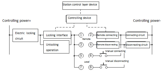 Picture 1 Schematic of Controlling Circuit of Remote Controlling Switch or Disconnector Monitoring device should support automatic output model and remote controlling output model of mal-operation preventing interface and exchange between these two modes. Under automatic output mode, monitoring device conducts mal-operation preventing logic judgments automatically. If the condition permits, the interface will close, on the contrary, the contact will break. . Under remote output mode, monitoring devices judge whether closing the contact by the mal-operation preventing logic of the object after receiving locking order from station layer device,. Afterwards, it conducts the logic judgment continually. If the condition doesn’t meet the requirements, the interface will break. After receiving the opening order from station layer device, the connection will close. Locking interface is closed for a long time, and then monitoring device will break the contact automatically. When the devices are abnormal or power-losing, the locking interfaces should be kept breaking broken. 6.3.3 Mal-operation Preventing Unlocking Switch Monitoring screen cabinet should provide switch which removes locking judgment. Mal-operation preventing unlocking switch should be controlled by key. 6.3.4 Sending of Mal-operation Preventing Condition Monitoring device can send the condition of mal-operation preventing logic and interface to the station controlling layer device. 6.3.5 Set Number of Mal-operation Preventing Data The device support function of remote number set, and the number can be replaced and involved in the logic operation of mal-operation preventing, which is convenient for the locking logic checking. 6.4 Mal-operation Preventing in Device Layer 6.4.1 General Requirements Primary device like disconnector and earth disconnector should be configured with mechanical or electric mal-operation preventing locking. When devices in spacer layer and process layer communicate through network, the smart terminal in process layer should output mal-operation preventing interface; receive the controlling signals output by devices in spacer layer through GOOSE; control the opening or closing of interface; and send the conditions of mal-operation preventing logic and interfaces of controlled objects. Electromagnetic locks and remote controlling air switch should be used to lock devices like manual operating device, network, and temporary earthing device for work. Monitoring system controls electromagnetic locks or remote controlling air switch by locking interface through cable. The position signals will also be gathered. Specific earth devices should be set in the earth interface of temporary earthing device for work in substation. Mal-operation preventing electromagnetic locks or specific earth devices should meet the requirements in JB/T 7827; should lock or unlock by the condition of locking interfaces in controlling device of monitoring system or smart terminal; should output the auxiliary interface which reflect operation condition of locks; and should have status indicator which indicates whether allowing unlocking and emergency unlocking mechanism. The position interface of mal-operation preventing electromagnetic locks, specific earth devices and remote controlling air switch should be connected into the corresponding controlling device and are involved in the judgments of locking logic condition. 7 Files of Mal-operation Preventing Rules 7.1 Component of File Rule files mainly consist of two parts which are part of signal dictionary and the part of operating rules. Signal dictionary mainly defines the involved data in mal-operation preventing rules to become more convenient for using. Part of operating rules is the list of controlling rules of operating targets. 7.2 Data Types and Operation Relations Operation of rules should support the comparing calculation of remote signals in single or dual position, integer and floating-point; support not logical operation of BOOL and precedence operation; and support the judgment of data quality. 7.3 Format of Rules File 7.3.1 Signal Dictionary The part of signal dictionary are expressed as follows [token dictionary] desc1 = data1’s name …… descN = dataN’s name Signal dictionary starts with the keyword “token dictionary”, and the keyword is in a separate line. Several signal definitions are arranged under the keyword, and each signal definition is in a separate line. Signal definition should avoid spaces or tabs. Desc, data string of data description, is made up of numbers and letters. It usually consists of mal-operation preventing number of primary device and attributes of data. Mal-operation preventing number is used for condition data information. Mal-operation preventing number and channel name is used for measurement data information, like 5011Ib. Mal-operation preventing number and CTL is used for control data information, like 5011CTL. Desc can be organized freely but must be clear for data without mal-operation preventing number. Data’s name should be consistent with data’s name in a database of monitoring system. In the substation which uses DL/T 860 rules, reference is used to show the data’s name. Reference should use ACSI way which includes data function restraint (FC). Controlled object is expressed as “FCD”. Position and measurement data is expressed as “FCDA”. For example, data’s name of controlled object can be: CB5011CTRL/QG1CSWI1.Pos [CO]. Data’s name of position information can be: CB5011CTRL/QG1CSWI1.Pos.stVal [ST]. Data’s name of measurement information can be: CB5011MEAS/Q0MMXU1.PHV.phsA.cVal.mag.f [MX]. In the substation which uses network DL/T 667(IEC 60870-5-103) rules, data’s name is presented in the way of “interval number + data type + data points”. For example, data’s name can be presented as “BAYxx.DOyy” for information of the controlled object. Data’s name can be presented as “BAYxx.DIyy” for information of remote signals. Data’s name can be presented as “BAYxx.AIyy” for information of remote measurement signals. 7.3.2 Operating Rules The part of operation rules is presented as follows: [operation rules] operateObject1’s desc{operateType}:logic expression1 …… operateObjectN’s desc{operateType}:logic expressionN Operating rule starts with the keyword “operation rules”, and the keyword is in separate line. Several operating rules of operated objects are arranged under the keyword. And each rule can occupy multiple lines from the first line. “Operate object’s desc” is defined in signal dictionary. “Operate type” contains two types which are closing and opening operation. “Logic expression” consists of desc, constants and operation signals defined in signal dictionary. For condition variables constant, “0” represents opening, “1” presents closing. The operation result “1” presents “permitting”, and the operation result “0” presents “not permitting”. Here are the definitions of operation signals: “=” is used to compare the variable and constant or variable. “>” is used to compare the variable and constant or variable. “>=” is used to compare the variable and constant or variable. “<” is used to compare the variable and constant or variable. “<=” is used to compare the variable and constant or variable. “&” is used in the logic and operation among BOOL amounts. “|”, which means “or”, is used in the logic and operation among BOOL amounts. “!”, which means “negative”, is used in logical negation operation among BOOL amounts. “()” is used in precedence operation in arithmetic expressions. The operations above are all half-width, operator precedence can be seen in chart 1. 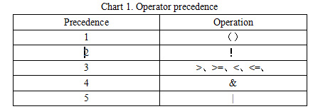 For example, closing operation rule of 5011 switch is: 5011CTL{closing operation}:((50111=1)&(50112=1)) | ((5012=1)& (5011Ia>100)) 8 Mal-operation Function DL/T 860 Information Interface 8.1 Control on Monitoring Device In the monitoring device which uses DL/T 860 standards, primary controlled objects such as switch and disconnector should use CSWI modeling. When device in station controlling layer control them, interlocking position which is defined as “Check” parameter of controlling service in DL/T 860.72 should be “1”. It means that control should meet the locking logic requirements. When operating conditions don’t meet the requirements, the reason of the client’s fault is presented as the negative response of locked-by-interlocking. Monitoring device should judge the “unlocking/interlocking” position. Judging mal-operation preventing locking will not be started when the device is on the unlocking position and will be started when the device is on the interlocking position. 8.2 Modeling of Mal-operation Preventing Function Mal-operation preventing function uses the modeling of CILO (interlocking control) logic node. If the interlocking condition meets the requirements, the logic node can be used in the permitted connecting and disconnecting operation. Each controlled object corresponds with an instance of CILO, the prefix and instance number of CILO should be consistent with CSWI. The data structure of CILO can be seen in chart 2. It adds two elements which are LckMod and EnaOp on the basis of DL/T 860.74. 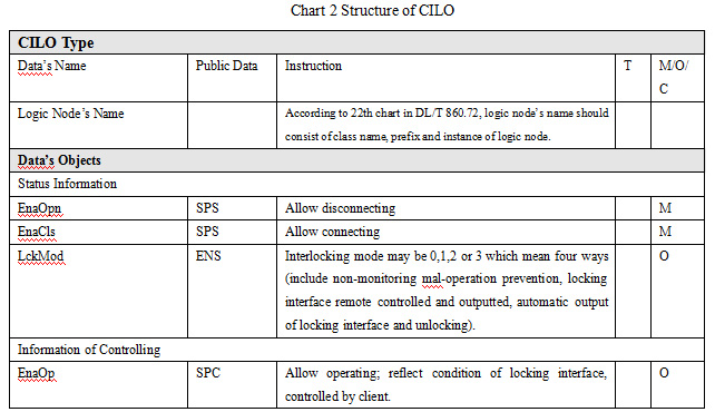 CILO reflects the judgment of mal-operation preventing logic. Mal-operation preventing rules can be described in the rules file. Data involved in rules operation must be in the modeling file of relevant devices. LcdMod reflects the interlocking mode of controlled objects. It can be one of four ways, non-monitoring mal-operation prevention, locking contact remote controlled and outputted, automatic output of locking contact and unlocking. Non-monitoring mal-operation prevention shows that controlling devices don’t have the mal-operation preventing judging function. EnaOpn is used to show the judging results of opening operation on controlled objects. EnCls is used to show the judging results of closing operation on controlled objects. EnaOp corresponds with mal-operation preventing interface of controlled objects. It can be controlled by the client. It can unlock the interface under connecting operation and lock under disconnecting interface. It needs five-defense judging under connecting operation and needs no condition under disconnecting operation. The remote controlling way of EnaOp is enhancing security and needs to be chosen and then operated. The relationships between EnaOp and LckMod are described as follows: When LckMode is under the condition of locking contact remote controlled and outputted, EnaOp can be controlled, it can unlock the interface under connecting operation and lock under disconnecting interface. The device outputs the remote controlling results according to the mal-operation in preventing interface. If condition is satisfied, remote controlling success; if not, remote controlling is fail. When LckMode is under the condition of automatic output of locking contact and unlocking, EnaOp cannot be controlled. The device does not accept the remote controlling order of five-defense contact, the condition of locking interface depends on the real-time condition of mal-operation preventing rules. When LckMode is under the condition of unlocking, EnaOp cannot be controlled. The device does not accept the remote controlling order of five-defense interface, the locking connect is locked automatically. The device is under the unlocking condition. When LckMode is under the condition of non-monitoring mal-operation prevention, EnaOp cannot be controlled. The devices don’t have mal-operation preventing locking contact. 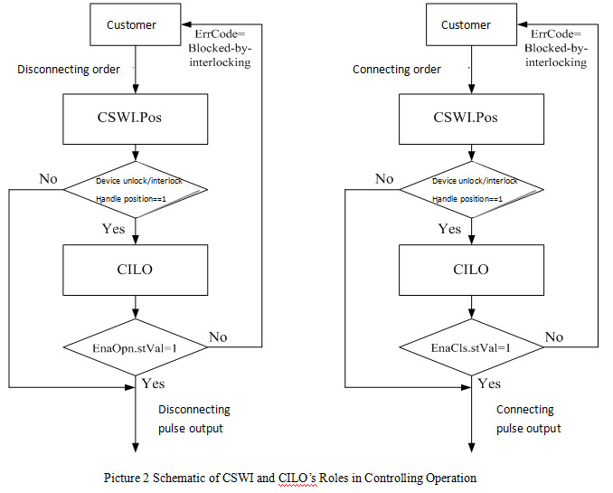 |
| 【close】 |